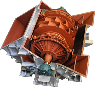
A rotary machine whose objective is to move air and gases by means of a turbine or motor that moves the impeller that sucks it in and subsequently expels it through its blades or vanes, modifying its direction with the incoming fluid.
OPERATION
Centrifugal fans are composed of a rotating impeller of blades (vanes) driven by an electric motor that moves the air, liquids or gases and expels them at high speed through the outlet cavity, cooling the space by removing hot air.
TYPES
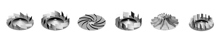
Centrifugal fans are classified according to the type of impeller or turbine used and their blades:
Centrifugal fan with straight radial blades It is the simplest, oldest, largest, and lowest performance type. However, they are self-cleaning due to the shape of the blades that prevents dust and dirt from sticking. Therefore, its most common application is the transport of granular or powdery materials.
Centrifugal fan with forward-curved blades They move a large amount of air thanks to the curvature of the blades and their arrangement in the direction of rotation. However, they are less efficient than the backward-curved blade type. Its application is popular for residential or commercial use due to its smaller size, which favors the absence of noise.
Centrifugal fan with backward-curved blades It is the type that offers the highest performance because the convex part of the blades moves in the direction of rotation, which favors air flow and prevents losses due to shock or eddying. This is the reason why it is the most widely used type of centrifugal fan. Likewise, they are self-cleaning and require little maintenance, which reduces their obsolescence.
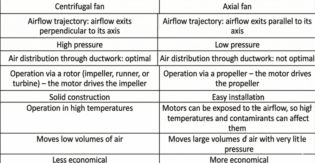
DIFFERENCES BETWEEN CENTRIFUGAL AND AXIAL FANS
APPLICATIONS OF CENTRIFUGAL FANS
- Water treatment plants
- Transport
- Smoke extraction
- Fluidized beds
- Cooling / Refrigeration
- Boilers and furnaces
- Ventilation
- Dust collection
- Combustion air
- Suction/Vacuum systems
- Mining
- Air conditioning
- Industry
CENTRIFUGAL FANS are strong and versatile rotating machines that move air or other gases in multiple industrial applications.
The fans we design cover every possible range of flow and pressure and are customized for each client, ensuring always the maximum efficiency and performance. Each fan is designed for a specific application which allows us to comply with all the regulations and standards required by a particular sector and a determinate client.
The experience obtained along our more than 100 years of history has provided us with a very solid background in almost all the applications in which centrifugal fans are required. Our fans are always designed to ensure that they will require the minimum and easiest maintenance.
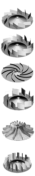
The efficiency of a fan greatly depends on the configuration of the impeller and its blades. Our designs have been tested to provide the maximum possible efficiency for each blade type. Considering the blade angle related to the fan rotation direction, we distinguish between three types of impellers:
Backward curved blades:
Depending on the application, they may be straight, curved or airfoil blades. The impellers designed with backward curved blades provide a very high efficiency (up to 90%) and are suitable for most applications since they achieve very good aerodynamics with little noise generation, proving high effectiveness. This is the most appropriate design when the fan conveys clean air or with few dust particles.
Radial blades:
Due to its configuration, this type of impeller is inferior in efficiency to those designed with backward curved blades. Its use is recommended for applications in which the fluids conveyed are dirty or have particles in suspension. The arrangement of the blades prevents the solid particles from adhering to them, therefore they can be considered as self-cleaning.
Forward curved or radial-tip blades:
This design is only and exclusively intended for applications with such a quantity of dust that makes it necessary to opt for a design that greatly prevents the solid particles from adhering to the impeller surfaces.
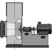
Drive through coupling. “D” arrangement:
The movement of the motor is transmitted to the fan by means of an elastic coupling. The impeller is fitted in a shaft that rotates on independent bearings or inside a strong bearing housing. This type of drive is recommended for continuous services and with hot gases.
Drive through pulleys and V-belts. “TVM” arrangement:
The use of pulleys and V-belts to drive a fan is recommended for all those applications in which the fan speed must be different to the motor speed. The motor is usually installed near the fan. Motor and fan casing have a common steel base.
Direct drive. “M” arrangement:
The impeller is directly mounted on the motor shaft. This is feasible when the fan is small in size, the required power is low and the fan rotation speed corresponds to the motor speed.
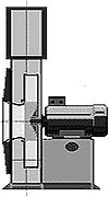
“EPDH” arrangement:
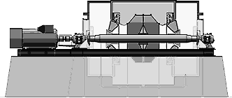
The single inlet fan is mounted between bearings on a passing shaft. The assembly is placed on an elevated structure made by concrete foundations. This is a non complex and very reliable arrangement. The bearing blocks are placed on pedestals of reduced height and the drive sits on a metal frame or directly over the concrete. The casing is anchored to the floor by means of its own frame.
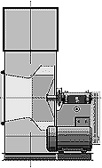
“BDH” arrangement:
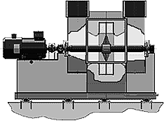
The double inlet fan is furnished with an integral frame that gives stiffness to the motor-fan assembly. This frame is anchored to a concrete foundation structure in which is lodged the lower part of the fan casing.
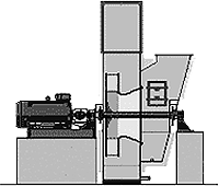
“BD” arrangement:
Double inlet fan mounted between bearings on a passing shaft. Fan and drive are arranged on an integral supporting structure equipped with vibration isolator blocks. This is an optimum disposition for fans that must be installed on structures exposed to vibrations. The antivibration blocks decrease the amplitude of the dynamic forces caused by the rotation.
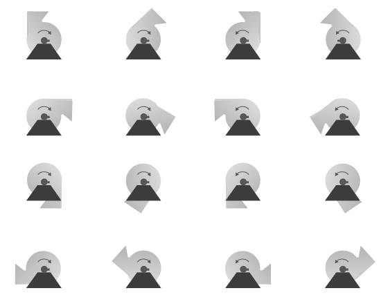
The impeller direction of rotation and fan discharge or outlet position should be chosen accordingly to the kind of installation in which the fan is integrated. It is the customer who sets these constraints. The reference orientation is marked in the adjoining figure as “GD360″ and refers to an impeller turning clockwise when the fan is viewed from the drive side. In this reference position, the fluid exits upwards in vertical direction. All the other standard discharge directions are shown in the figure. We can also supply fans with the discharge directed in a different angle not shown herein.
GRUBER HERMANOS, S. A. offers full guidance for the selection of any kind of fan, whatever the application might be. The fan design starts in the technical-sales department with the selection of the type of fan that better conforms to the volume and pressure data provided by the client. Considering each application, the most suitable materials and designs must be selected according to the fan planned service and location in the plant.
These are some examples of fan characteristics depending on the applications for which the machine is intended:
FANS FOR ENERGETIC GASES: Very strong design. Gas tight executions. ATEX non-spark executions.
FANS FOR CORROSIVE GASES: Made of stainless steel. Rubber lined impeller and casing. Casing made with silica casting.
FANS FOR HOT GASES (Up to 900 °C): Supported at shaft level. Made of refractory steels. Oil lubricated and water cooled bearings.
FANS FOR FLUIDS WITH ABRASIVE DUST IN SUSPENSION: Radial or backward curved blades. Made of abrasion resisting steels and fitted with liners of the same material in the areas of maximum wear.
FANS WITH HIGH PERIPHERAL SPEED: For pressures up to 3000 mm.w.g. having only one compression stage. Made of special plate with high elastic limit.
FANS WITH SEVERAL COMPRESSION STAGES: They can reach pressures up to 8000 mm.w.g.
Considering each application, the most suitable materials and designs must be selected according to the fan planned service.